


STANDARD DESIGNS AND ESTIMATES
for Used Water Management and Faecal Sludge Management
Standard Drawings and Bills of Quantities for UWM infrastructure to support tendering processes
SELECT YOUR SOLUTION TYPE (Wastewater Treatment)
{{ solution.name }}
{{ solution.description }}
SELECT YOUR SOLUTION TYPE (Faecal Sludge Treatment)
{{ solution.name }}
{{ solution.description }}
SELECT TECHNOLOGY
{{ tech.name }}
{{ tech.description }}
About {{ selectedTechnology.name }}
 Working Principle:
Soak pits are unlined or partially lined circular pits designed to allow used water to
percolate directly into the surrounding soil through a filter media. The pit is typically
filled with coarse materials such as rubble or brick bats, which create voids to facilitate
infiltration and prevent immediate clogging.
A removable top cover should be provided to allow for regular inspection and maintenance. To
enhance system performance and minimize clogging, it is recommended to use a settling tank
as a pre-treatment step before the water enters the soak pit.
Suitability:
Soak pits are mostly used at the household level where the volume of used water is low,
particularly for the disposal of supernatant from septic tanks. They are suitable in areas
where the soil has good infiltration capacity, and the groundwater table is low (at least
1.5 meters below the bottom of the soak pit).
They are not suitable for: Flood-prone areas, Clayey or rocky soils, Soils with low
permeability
Pros/Cons:
Pros: Most economical option for small capacities
Cons: Cons: May negatively affect soil and groundwater properties as it does not provide
adequate treatment, and the pit will quickly clog.
O&M requirement:
Particles or biomass may clog the pit so cleaning or replacing the filter material once in 2
– 3 years or or sooner if overflow or surface pooling is observed in the surrounding area.
 Working Principle:
The working principle of a leach pit is similar to that of a soak pit, with one key
difference: the pit is not filled with any filter media. It is an unlined or partially lined
circular pit designed to allow used water to infiltrate directly into the surrounding soil.
The structure is typically constructed using brick masonry or pre-cast concrete rings.
Unlike a soak pit, which contains rubble or brick bats to aid filtration, the leach pit
remains empty, allowing for increased hydraulic retention time—particularly useful when
managing higher volumes of used water. This design facilitates gradual percolation of the
water into the soil.
A removable top cover must be provided to enable periodic inspection and maintenance. To
improve system performance and reduce the risk of clogging, it is recommended that settling
tank be used as a pre-treatment step before water enters the pit.
Suitability:
Leach pits are primarily used for the disposal of used water, particularly greywater from
households or from drain endpoints where the volume is relatively high (up to 10 KLD). They
are suitable in areas where the soil has good infiltration capacity, and the groundwater
table is low (at least 1.5 meters below the bottom of the soak pit).
They are not suitable for: Flood-prone areas, Clayey or rocky soils, Soils with low
permeability
Pros/Cons:
Pros: Can be built and repaired with locally available materials, Low capital costs; low
operating costs, small land requirements
Cons: May negatively affect soil and groundwater properties as it does not provide adequate
treatment, and the pit will quickly clog.
O&M requirement:
Over time, fine particles, silt, or biomass may accumulate within the pit or around its
infiltration surfaces, leading to reduced percolation efficiency. Periodic inspection is
recommended, and the pit should be cleaned or desilted every 2–3 years, or sooner if
overflow or surface pooling is observed in the surrounding area.
 Working Principle:
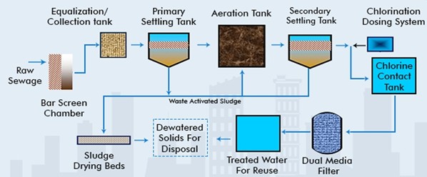
The EA-ASP is a modified activated sludge process that operates with extended aeration and
longer sludge retention times, enhancing biological treatment of used water. In this system,
wastewater is continuously aerated in an aeration tank to promote microbial degradation of
organic pollutants. A secondary clarifier follows to separate treated water from the
biomass. The extended aeration reduces sludge generation and stabilizes organic matter more
effectively. EA-ASP is simple to operate, reliable, and suitable for small to medium-sized
towns with moderate flow variations.
Suitability:
Suitable for small to medium towns with consistent flows and loads.
- Preferred where land availability is moderate, and energy costs can be managed.
- Ideal for locations with limited technical staff, as the system is relatively simple.
- Well-suited for decentralized or peri-urban setups.
- Good choice for ULBs preferring robust, easy-to-operate systems.
Pros/Cons:
Pros: Simple to operate and maintain, well-stabilized sludge, Robust system for consistent
flows, no complex automation required
Cons: Requires large land area, higher civil construction footprint, limited flexibility for
load fluctuations, energy demand for aeration
O&M requirement:
- Simple operation; minimal instrumentation
- Regular aerator/blower maintenance
- Periodic sludge wasting (less frequent due to extended retention)
- Occasional tank cleaning and removal of scum/foam
- Suitable for operators with basic technical training
 Working Principle:
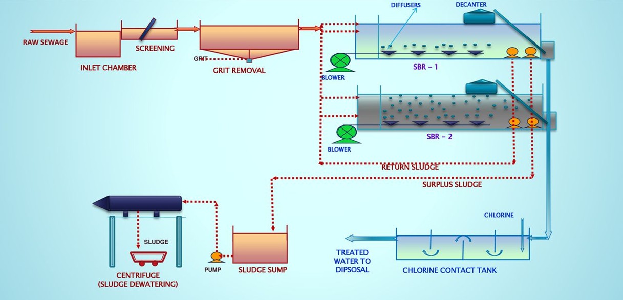
The SBR is a fill-and-draw type activated sludge process where all treatment
steps—equalization, aeration, and sedimentation—occur sequentially in the same tank.
Wastewater is added in batches, treated biologically through aeration, and then allowed to
settle before the treated effluent is discharged. The process operates in defined cycles
(e.g., fill, react, settle, decant, idle) controlled by automation. SBR systems provide
effective removal of BOD, COD, and nutrients. They are space-efficient, flexible for varying
loads, and suitable for decentralized and municipal sewage treatment.
Suitability:
Suitable for medium to large towns with with automated operations and moderate to high used
water volumes.
- Works well in space-constrained locations due to compact footprint.
- Best suited for areas with skilled operators and where automation and reliable power
supply are available.
- Can handle flow and load variations, making it good for municipal use.
- Ideal for automated, time-sequenced operations in urban settings.
- Where higher treatment efficiency required
Pros/Cons:
Pros: Compact and space-efficient, high treatment efficiency (BOD, COD, nutrients), Flexible
to flow/load variations, fully automated with minimal operator intervention during operation
Cons: Requires highly skilled operators and automation, high energy demand, sensitive to
power failures, higher O&M complexity
O&M requirement:
- Requires skilled operators to manage automated cycle phases (fill, aerate, settle, decant)
- Daily monitoring of SCADA/PLC system
- Regular inspection and calibration of valves, pumps, timers, and decanters
- Sludge removal at defined intervals
- Power backup systems needed due to reliance on automation
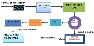 Working Principle:
The MBBR system is a compact, aerobic biological treatment process that uses suspended
plastic media (carriers) within an aeration tank to support biofilm growth. As used water
flows through the tank, microorganisms on the media degrade organic pollutants. Continuous
aeration keeps the media in motion, enhancing contact between the wastewater and biofilm.
The system requires a secondary clarifier for solid-liquid separation. MBBR is
energy-efficient, has a small footprint, and performs well under variable loading
conditions. It is suitable for treating municipal sewage and can be used for upgrading
existing systems.
Suitability:
- Suitable for small to medium towns with space limitations.
- Good for areas with moderate to variable organic loading.
- Suitable where biological treatment is preferred with less operator intervention.
- Performs efficiently under shock loads and flow variations.
Pros/Cons:
Pros: Compact footprint, handles load fluctuations well, low sludge generation, easier to
operate than SBR, suitable for retrofitting/upgrading existing plants
Cons: Continuous aeration required, moderate energy consumption, biofilm media needs
monitoring/replacement, not ideal for high nutrient removal
O&M requirement:
- Routine monitoring of aeration system (blower operation, DO levels)
- Periodic cleaning/checking of diffusers and carrier media
- Occasional inspection of media retention screens to prevent clogging
- Sludge removal from secondary clarifier as required
- Lower operator skill requirement than SBR
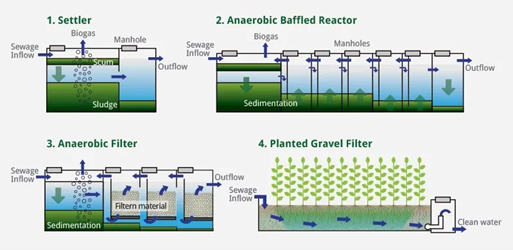 Working Principle:
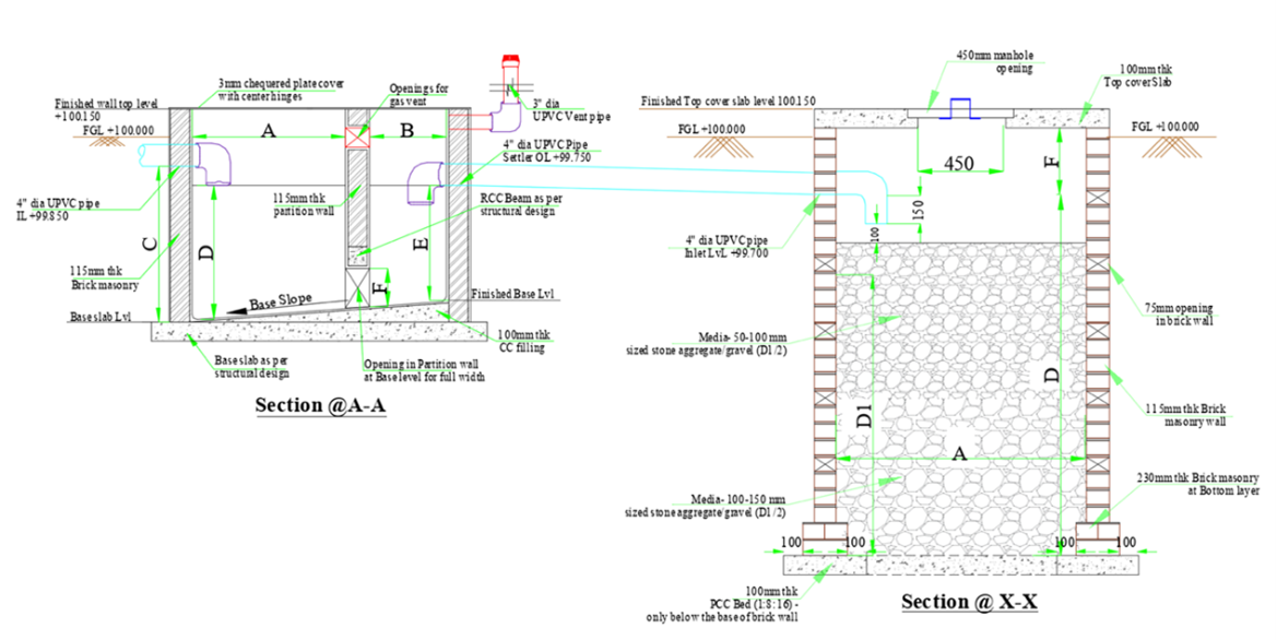
DEWATS systems are based on modular technical configuration concept. Modules chosen for used
water treatment consist of Settling tank (ST) for primary treatment, Anaerobic baffle
reactor (ABR) with integrated filter (AF) for secondary treatment and Horizontal flow
planted filter (HFPF) for tertiary treatment, polishing pond (if required for post
treatment). Used water is passed through all these modules in sequence for treatment.
Suitability:
DEWATS (Decentralized Wastewater Treatment Systems) are designed based on the principle of
low maintenance and energy-efficient operation. The modular combination of DEWATS components
is well-suited for treating used water generated from housing communities or collected from
drain endpoints with high volumes of used water. The treated effluent typically meets
quality standards for safe reuse, particularly for landscape irrigation and non-food crops.
Pros/Cons:
Pros: DEWATS modules can be built and repaired with locally available materials and do not
require energy or skilled labour and low in operations and maintenance cost as compared to
electro-mechanically operated technologies. The units can be designed and easily integrated
to blend with the surrounding landscape and produce a good quality effluent that can be
reused.
Cons: Area requirement and capital cost is moderate to high.
O&M requirement:
Regular emptying of sludge (once in 2 to 3 years) and scum (once in 6 months) from ST and
AF, cleaning (or replacement) of filter media once in 3 to 5 years in the AF and HFPF,
harvesting of plants in the HFPF.
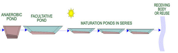 Working Principle:
Waste Stabilization Ponds (WSPs) are large, human-made water bodies in which used water are
treated by naturally occurring processes under the influence of sun light, wind,
microorganisms and algae. The ponds can be used individually, or linked in a series for
improved treatment. There are three types of ponds in series (1) anaerobic, (2) facultative
and (3) aerobic (maturation), each with different treatment and design characteristics.
Suitability:
Waste Stabilization Ponds (WSPs) are appropriate for towns and cities with large, open, and
unused land areas, preferably located away from residential zones and public spaces. They
are particularly well-suited for tropical and subtropical regions, where ample sunlight and
warm temperatures enhance the natural treatment process. WSPs are especially effective for
treating used water collected from drain endpoints, particularly where high volumes of used
water are generated. The treated effluent is generally of a quality suitable for irrigation
and agricultural reuse.
Pros/Cons:
Pros: WSPs are low capex and opex based system, can be built and repaired with locally
available materials, system does not require electrical energy, basic skill requirement for
O&M, can produce good quality effluent which is safe for its reuse.
Cons: WSPs require a large area. Ponds require regular sludge removal (especially anaerobic
pond) to avoid excessive accumulation, as removing large volumes at once can be
time-consuming and difficult to manage. They may produce undesirable odors, and mosquito
control is required.
O&M requirement:
Scum that builds up on the pond surface should be regularly removed, aquatic plants that are
present in the pond should be removed as they may provide a breeding habitat for mosquitoes
and prevent light from penetrating the water column. The anaerobic pond must be de-sludged
approximately once every 2 to 5 years. De-scumming and de-sludging of ponds need to be
carried out as per the schedule to avoid odor nuisance.
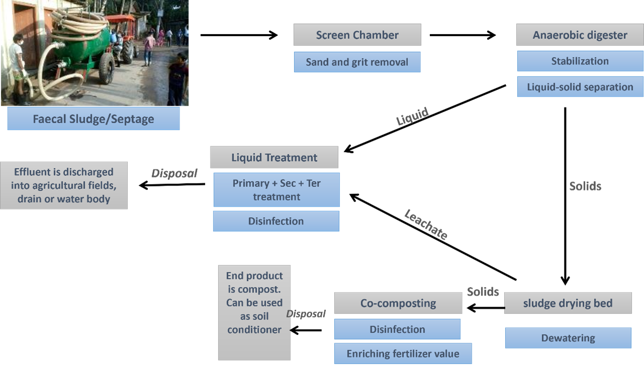 Working Principle:
Sludge Drying Bed (SDB) is a shallow, rectangular structure filled with layers of graded
filter media, typically comprising sand and gravel of varying sizes and thicknesses. The bed
is generally open to the atmosphere and is equipped with a drainage system at the base to
collect percolate or leachate. An anaerobic digester can be deployed for digestion of sludge
before application on the sludge drying beds, if required. Sludge is applied evenly over the
top sand layer, and water drains through the filter media by gravity. An underdrain system
collects the leachate, which is then directed either to a liquid treatment facility for
further treatment. In addition to percolation, surface evaporation accelerates the drying
process. The dried sludge is manually removed, usually after 10–15 days, depending on local
climatic conditions and sludge characteristics.
Suitability:
- Suitable for small to medium towns with moderate sludge generation.
- Ideal where land is available, and climate is warm and dry.
- Can be used where periodical sludge removal is feasible manually.
- Suitable where no skilled manpower or electricity is available.
- Can be adopted where mechanical drying is not preferred or practical.
- Effective in remote locations with basic infrastructure
Pros/Cons:
Pros: Simple to construct and operate, low capital and operating cost, no energy or
mechanical equipment required, uses locally available materials
Cons: Requires manual removal of sludge periodocally, drying time depends heavily on local
weather conditions, can produce odor if not properly managed, prone to clogging over time,
frequent maintenance of sand layer needed
O&M requirement:
Periodic removal of dried sludge (typically every 10–15 days depending on drying time)
Regular cleaning or replacement of the sand layer to prevent clogging
Monitoring of drainage system to ensure proper leachate flow
Odor control through proper loading and timely sludge removal
Maintenance of bed leveling and weeding if any vegetation grows unintentionally
 Working Principle:
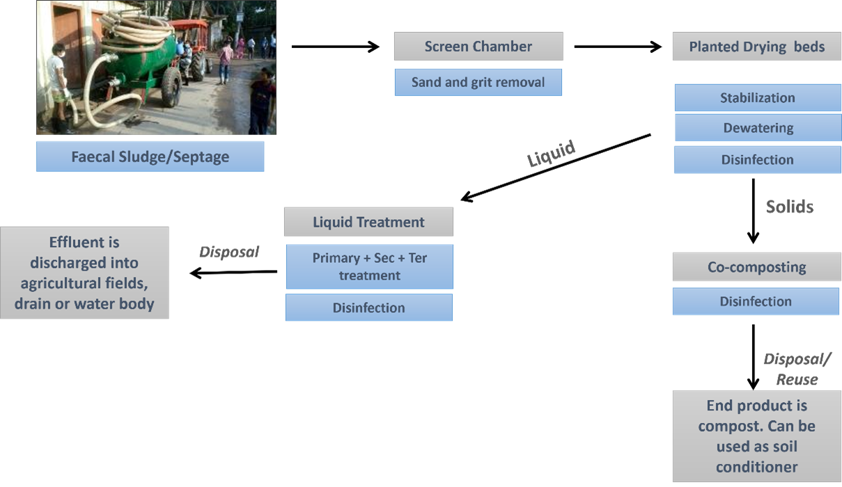
Planted Drying Bed (PDB) is a shallow, rectangular bed consisting of multiple layers—coarse
gravel at the bottom, a sand filtration layer in the middle, and a top layer planted with
specific wetland vegetation such as Canna indica or Phragmites australis. The bed is open to
the atmosphere and equipped with a drainage system at the base to collect leachate or
percolate. Sludge is applied uniformly over the sand surface, and water percolates downward
through the filter media by gravity. The leachate is collected by an underdrain system and
directed to a liquid treatment facility for further treatment.
The vegetation plays a critical role in enhancing treatment performance. Plants promote
drying through evapotranspiration, improve infiltration through root channel formation, and
facilitate aerobic microbial activity that aids in sludge stabilization. Nutrient uptake by
plants also contributes to improved leachate quality,
Suitability:
Suitable for locations with limited human resources where frequent sludge removal is not
feasible
Suitable for small to medium towns with moderate sludge generation.
Performs well in tropical/subtropical climates with adequate sunlight.
Ideal where better sludge stabilization and odor control are required.
Useful in locations with high organic sludge content, requiring improved stabilization.
Pros/Cons:
Pros: Faster and more efficient drying due to plant-assisted evapotranspiration, improved
sludge stabilization and reduced odor, lower risk of clogging due to root channels, reduced
sludge handling frequency, contributes to a greener, nature-based solution
Cons: Slightly higher land and construction requirements, requires periodic plant harvesting
and care, may require more time to establish (plant growth phase), performance may vary with
plant health and season
O&M requirement:
Sludge removal every 1 to 3 years depending on design, sludge loading and drying time.
- Regular harvesting or pruning of plants to maintain root health and effective
evapotranspiration.
- Monitoring plant health, replanting if mortality occurs.
- Occasional de-weeding to avoid invasive growth
- Maintenance of Sand layer
- Check and maintain leachate drainage system.